Sunday 7 December 2014

Linear Carriages

I have started printing the linear carriages and the first batch have turned out well.   They are designed to have 2 x LM12LUU linear bearings fitted, which are clamped by the means of 4 x M4x16mm cap screws and 2 circlips on  each bearing to stop it moving up and down.  They were printed on my Up Mini at a resolution of 0.2mm, fine quality and 1/4 fill to keep the weight down. I will say though, make sure the part is printed with teh pockets for the balls facing upwards and if facing down, even with smart support the pockets are not radiused correctly.

I  am using GT2.5 open ended belts so the carriages are designed to grip both ends.  I printed and tried a few integrated belt gripper designs before I settled on the one below.  It is made so the belts pass over each other and are secured so the ends pull from the opposite side of the carriage, pulling the print layers together, not apart like it would if each belt was attached from the top and bottom.  This is important especially if the chamber is heated as I don't want any delamination of the part.   This also means I don't need to worry about too much belt tension breaking anything.   A 6mm  long piece  of 1.75mm filament is pressed into the eye where the belts fold over and becasue the teeth mesh together they cannot pull out. I yanked on both belts really hard and there was no movement so I am very happy.

carriage with belt fitted and securing nuts and bolts

close up showing the belt fed into the carriage and the small pieces of filament
locking the end loops

The belt grippers are located dead centre between the linear rods in both the x and y direction so there will be lateral forces on the bearings from the belt pulling the carriage up and down.   This also means that the steppers are mounted off centre to keep the timing belt centered to the carriage.

Like the end effector each carriage has a 10mm diameter N42 magnetic ball JB welded to it.

Complete carriage assemblies fitted

close up of the
 carriage assembly with bearings fitted

Friday 5 December 2014

End effector and hot end fabrication and assembly

Well I think the design is pretty much finalised so I have started to machine and print parts and assemble them.

First up was the hot end.  It was cut from a single piece of alloy bar on my lathe and then the 5 mounting holes drilled on my mill. I still need to machine the stainless heat break and alloy heater block however which is planned for this weekend.  I am still tossing up making my own extruder nozzles but for the cost it would be just as easy to purchase them.


cutting heatsink grooves with parting tool


Tapping the M6 thread for the pneumatic fitting and heat break

Drilling the holes using the mill with DRO and the circular pattern function

The next task was to print the end effector on my UP Mini printer.  I ended up using the fine print speed, 0.2 layer height and 1/4 fill just so the sockets for the magnetic balls were nice and accurate. I have modded the heat bed on my Up Mini so it runs at 80ºc which stops parts warping.  I also used the new Verbatim filament and am very happy with the results.  The raft and supports came away from the printed part quite easily.

My design uses six N42 10mm diamter magnetic balls that are glued into the effector sockets with JB weld. It must be said however that this process was harder than expected and if I was to do it again I might use plain ball bearings and magnets in the rods.  The reason for this is the magnetic balls are just so strong.  Even at 60mm apart then will attract eachother as can bee seen in the video below and if you get too close they will jump out of the sockets and stick together

                                                   
As you can see as soon as soon the balls are put in place their poles align and if one is rotated, the other moves.  This is important to remember before scuffing the magents so the JB weld has something to stick to.  What I did was place the magnets and marked their tops with a niko pen, then scruffed the oposing side with some 240 grit emory tape.  I was only able to glue magnets at a time however and needed to wait 24 hours for the glue to set before attaching the next ones.   I also found I need to wrap the magents that had already been glues with a tissue befoer gluing the next becasue if the next ball to be glues jumped out of the socket, it could hit the already glued ball with enough force to break the glues and knock the ball from the socket.

The effector was prepared by scuffing the socket with emory, drilling some 1.5mm holes so the glue had a little more to key into, then cleaned both the socket and balls with isopropyl alcohol

end effector sockets scuffed and drilled ready for the balls to be glued
Once all the balls were glued, the hot end, fan duct and 40mm fan were attached using M4 bolts and nuts.  This ensures a nice stong attachment that will not come loose or flex which will increase the overall accuracy of the printer.  Weight wise the complete end effector weighs 135 grams 


 I have also designed and printed a twin extruder end effector but have not made the hot ends yet.  It is the same footprint as the above effector which will make the tuning much easier. I also disigned adaptors for the E3D-V6 hotends just in case I didn't have time to make my own. An adaptor was also designed for the singel extruder above.   Again the aim here is to make things as rigid as possible.


end effector with 40mm fan and dual coling duct attached


More parts have arrived, including the 6mm alloy plate, carbon fibre rods and the 30x30 extrusion for the frame so lots more to do.

Will post more soon.

Monday 1 December 2014

Verbatim 1.75mm ABS filament quick review

A few weeks back i purhcased some of the new 1Kg Verbatim 1.75mm ABS filament form RS components to see what it is like and I have to say I am very very happy with the quality of the filament and the print results.

The filament is made in Japan and comes vacuum packed in plastic then packed in a cardboard box which is great as it protects the filament properly.  Dimensionally the filament I tested was spot on 1.75mm with no variance on the spool I received.  The 005000-812 black filament prints with a nice high gloss at 235ºc extruder temperature and the supports and raft were nice and easy to remove from the print,   something I have struggled with other generic ABS filaments.

The 53mm spool core diameter is bigger than most so I designed and printed a reducer with a 22mm bore so I could use my standard spool holder on my printer. The .stl file for it be found here 

So all in all I will continue to use the Verbatim ABS.  I have some other colours to trial but if they work as well as the Black, I will not be dissapointed.

Tuesday 25 November 2014

the Delta 3D design process begins

Although I am still in the design stage of this build, like their cartesian counterparts there are many ways to tackle the delta printer build and I can see the design evolving as each part is manufactured and installed.  I spent time looking at the Kossel and Rostock printers and was very impressed with their design so for my printer the following list of questions was compiled:

          - what build volume do i want
          - should i use an off the shelf hot end or custom make one
          - magnets vs rod ends vs bearings for the end effector mounting
          - linear rails vs rods vs v-groove wheels for the vertical movements.
          - timing belt or dynema for moving the carriages
          - best method for heating the bed
          - how to achieve the best rigidity to keep print quality high and enable higher print speeds.
          - twin vs single extruder

Build Volume:

This was probably the easiest part.  300mm diamter x 400mm high.  The 300mm diameter  means I can print a 200x200mm square in that area which is about the biggest thing I can think of printing at the moment.  But this also gives me some room to breath outside that area being able to print up to 280mm diameter.

Bed Heating:

I print everything in ABS so a heated bed is a must so what are my options?

I found it is very easy to find 214mm square heat beds jstt about anywhere at very low prices but not so easy to find the larger circular heat beds.  I did find a 310mm onyx heated bed  that will fit the bill perfectly which can be coupled with a Rostock glasss build plate.  These would certainly make the build a little easier but with overseas postage the cost will mount up.

So what other options are there.  Well, I recently build a heat treat oven for tempering knife steel.  For this build I made my own elements from Kanthal A1 wire.  The process is quite simple, choose the diameter of the wire,  and with some maths calculate the madrel diamter, ohms required for the wattage required then using a lathe wrap teh wire around the mandrel, stretch it out and you have an element.  The element can run in grooves cut in some fire board.   However, because these run off mains voltage for safety you need a cicuit breaker, solid state relay for switching, good quality thermocouple and controller, a means of isolating the element wire properly from the printer frame and yourself.  So at this point option one doesn't look too bad.  Isn't as DIY but is certainly simpler, especially for those who may not have electrical experience.
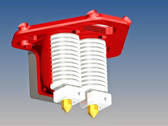
Hot Ends:

There are too many hot ends to list but since I have a lathe I have opted for a custom all aluminium one with a 40mm fan and duct to cool it down.  I also have the ptfe running nearly all the way down to the heat break to keep jamming at a minimum.   It looks like this


The aim of this design was to have plenty of cooling whilst keeping the head as secure as possible to the end effector, again to keep print quality as high as possible.  This is achieved by bolting the flange with 5 x M4 nuts and bolts to the effector.  She isn't going anywhere.

I also have plans for an auto level hot end but that is still in the design stage.  Again rigidity and simplicity is key but also precision.

Magnetic End Effector

I have settled on and ordered 10mm magnetic N42 balls from Frenergy Magnets.  I chose magnetic balls because to me they will work well, have no maintence and no backlash to contend with.  Plus given the low weight of the effector should have no issues with strengh and magnets enable quick change overs between heads or for maintenance.

I have designed and printed 2 effector versions, a single and double extruder as seen below.  Both use a 40mm 12v fan with duct to cool the hot end and both have been designed to enable the use of E3D hot ends by using adapters I also made.


Frame

My frame will be rigid, using 30x30 aluminium extrusion and 6mm aluminium plate for the floor, ceiling and heater plate support.  This decisoin was made primarily to allow for faster speeds without vibration or flex.  Whether this will pan out is yet to be seen but better to plan for the worst case scenario than with I had done it defferently down the track.   The use of alluminium plates will also negate the need to print corner peices, making the build faster.

The shape I have chosen will enable a full perspex cover to be added to the printer which will serve a few purposes.  Safety to keep little finger out, keep the heat in for those larger prints, but also to act a fume cupboard so I can extract the ABS fumes away safely without stinking out the house.

This is a mock up of  the unit so far


All electrical stuff will be contained under the heat bed suporting plate.  This will add additional weight to the bas eand add stability, enable cooling of all the parts with a single fan and keep things pretty.

Dimension wise the printer will be 900mm high and 510mm at the widest point.

Linear Bearings:

This has been the hardest choice and to be honest my decision for the first build is based on cost.  I have used Hiwin linear bearings and rails in many automation projects and as ideal they would be for this project I cannot find them cheap enough to be worth it.  Even using HGW15 bearings and rails is quite costly.

So I am going to use 12mm linear rods and bearings and 3D print bearing supports to suit.  To be hoenst I cannot see these will not be accurate enough, especially with the 30mm square extruded uprights as well.  It also means I can upgrade down the track if the rods prove to be not up to the task.


So,,  that's  my progress.   I have magnets, alloy extrusion and carbon fibre rod being delivered soon and more designing to complete, then decision on which control boards and steppers to use.

Thanks for looking.

And the journey starts

This is my first dabble in a blog so hello to all

My interest in 3D printing started quite by accident.  I purchase Austodesk Inventor and included with the CAD package was an UP! Mini 3D printer.  It sat in the box for about 3 months as I could not think of any reason I would have need of or use a 3D printer.  Fast forward to the Christmas holidays and bordem, I opened the box, set it up and started printing parts for Mountain bike lights I build and I haven't stopped printing since.  I was and still am amazed at what we can produce with our printers and just how quickly and idea can be brought to life.

So this brings me to where I am now.  As great as the UP! Mini is I have always wanted something bigger to save having to print multiple parts and glueing them together. The other problem with a smaller print area is it can meke it difficult to orientate your print job so it has the greatest strength buy taking advantage of the layer direction .   To that end I have spent quite some time over the past few weeks researching printers available today.  I could have gone the simpler route and build a standard cartesian printer but loving delta robots decided on making a Delta 3D printer.  There is just something about the theatre of the way they move and having a static stage to print on make sence when higher speeds are desired.

More to come